Create a face
⚠️ Please note: If your face contains stacked pallets, it will be necessary to configure your cartography by following the Configuration process in case of stacked pallets.
To create a face there are 2 possible locations in the EYESEE Cloud:
- In the zone list, click on the one you want to create some faces in
- In the faces list
And 2 ways to create it:
- Without CSV file, with the integrated locations naming
- By importing a CSV file
1. Face creation without a CSV file, with the integrated locations naming

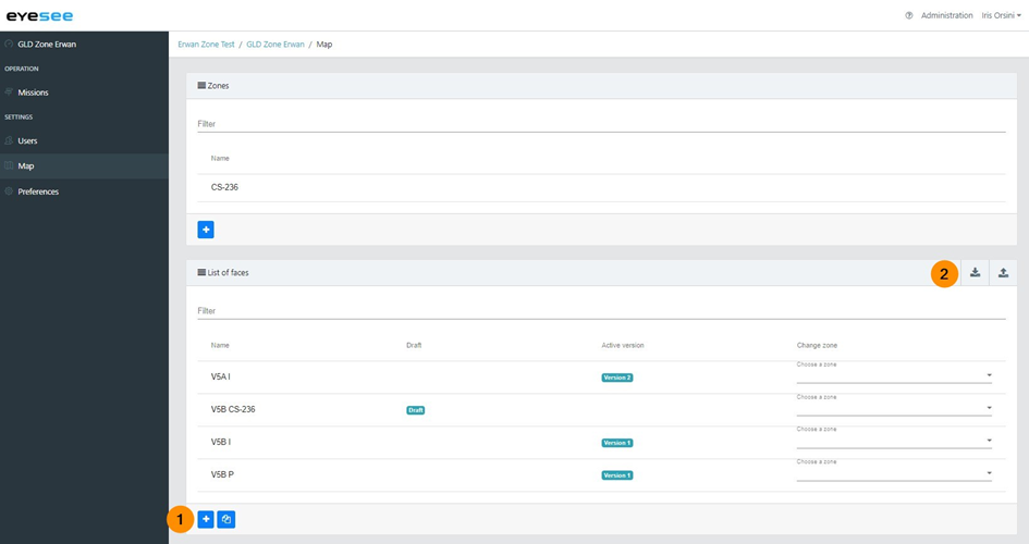
1. In the faces list, click on the add icon.
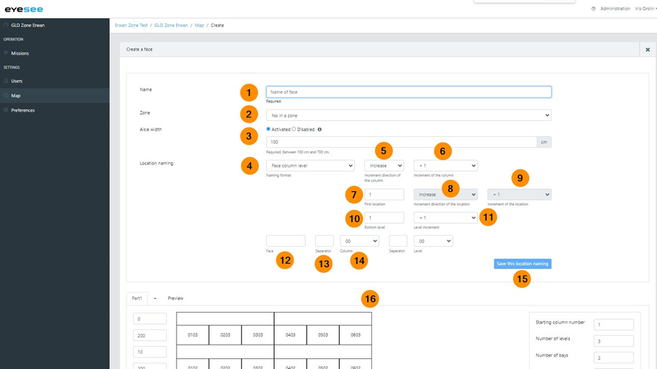
2. Enter a name.
3. Choose the associated zone
4. Enter the aisle width (in cm) where the face is. It is enabled by default. If the width is variable, it is possible to disable the aisle width. In this case, its value is automatically set by default to 700cm and cannot be changed. To change the width of this aisle, you must check “Activated” again. Hovering the mouse over the small “i” icon displays the meaning of this field.
The next concerns the naming of the locations. Once it is defined, the next part is the configuration of the face itself.
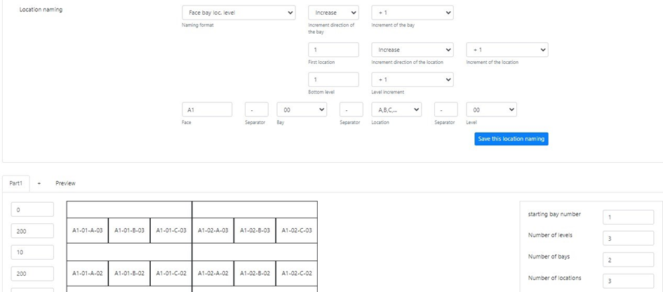
Step 1: location naming
The order of some configuration elements depends on the selected naming format.
Choose:
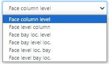
5. The naming format from the following choices:
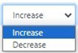
6. The increment direction of the column (or bay according to the format choice):
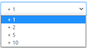
7. The increment type of the column (or bay according to the format choice):

8. Reverse or not the location letter increment (only for the 4th last formats and IF the location name is a letter or two).
9. Bottom level: by default, the value is defined to 1
10. Level increment from the following choices:
11. Face name (by default, it is dynamic according to the name written above, you can modify it).
12. A 1rst separator if there is one, if not, let the field empty.
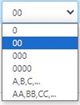
13. Column name format (or level or bay according to the selected format) from these next formats:

14. A 2nd separator if there is one, if not, let the field empty.
15. Level name format (or column or bay or location according to the selected format) from these next formats:
For the last 4th format choices from the list, two other fields appear:
- A 3rd separator if there is one, if not, let the field empty
- Level name format (or bay or location according to the selected format) from these next formats:

16. The display is dynamic according to the different settings, which allows to see immediately if the naming format matches the real face.
Configuration example with a naming format ‘Face bay location level’:
Step 2: Face configuration
Once the location naming is defined, the configuration of the structure elements of the face allow to concretely visualize it.
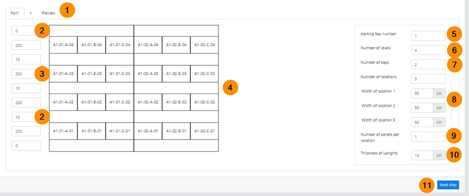
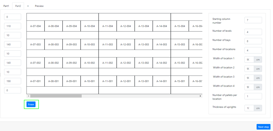
The tabs ‘Part1‘, ‘+‘ allow to add tabs to configure a part of the face different from the current one. For example: the first 2 bays contain 3 columns and will be configured in the ‘Part1’ tab, the other bays of the face contain 4 columns. By clicking on the ‘+’ tab, a ‘Part2’ will be added to configure these bays. In this case, the name of the columns is incremented. It is also possible to change the number of the starting column in the field n°4. It is possible to add several tabs, for example:

If a tab is added, configure the affected bays in the same way. An “Erase” button allows you to remove the current tab :
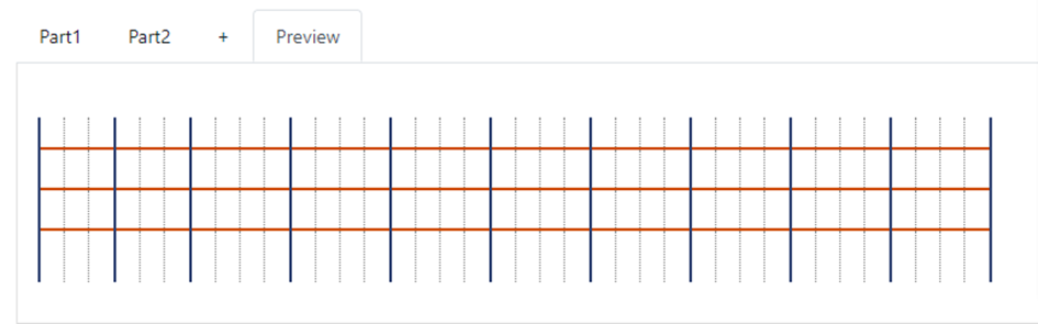
The ‘Preview’ tab allows to view the face as it will be created in EYESEE Cloud. When moving the mouse over the locations, the location name is displayed.
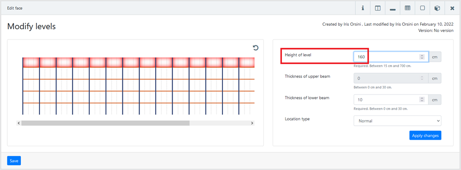
2. The values of these fields correspond to the beams’ thickness in cm. By default, the beam below the first level and the beam above the last level are set to ‘0’. The values of the other beams are set to 10cm by default.
3. The values of these fields correspond to the heights of the levels without beams in cm. For the last level height: it is recommended to not enter the total value of the last level (unless the label is positioned at the top of the pallet). Define a 30cm smaller value to avoid unnecessary movements of the drone and the possible detection of obstacles. Ex: The height of the highest level is 140cm, so the value entered should be 110cm.
4. Dynamic display according to the configuration
5. The starting column number of the face (Ex: 1, 2, 90, etc.). The names of the following columns will be automatically incremented according to this value.
6. Levels number
7. Bays number
8. Location number per bay (between 2 uprights)
9. Bays width in cm (depending on the bays number defined in the field above)
10. Pallets number per bay
11. Uprights thickness in cm
12. Visualization of the tab configuration
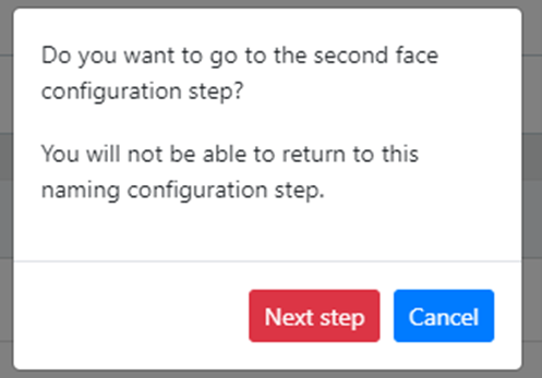
13. Click on “Next step” once you have completed this configuration and visualized the face using the “Preview” tab. You will not be able to return to this configuration screen. A confirmation message appears when you click on “Next Step”:
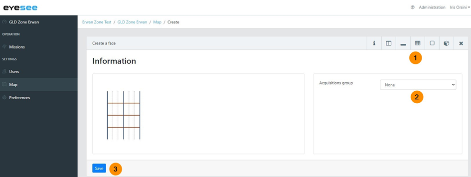
By clicking on ‘Next step’ to continue the configuration of the face, this screen displays:
The face is not created yet.
1. Check the configuration by clicking on the icons, Modify bays, Modify levels, Modify slots, Modify locations, Manage flight constraints, to add flight constraints if necessary (Not used locations: the drone flies / can fly in front of the location but does not take any acquisitions. Flight prohibited : the drone is not allowed to fly in front of the location, it is forbidden (ex: a forklift crossing point, a girder, a firebreak, etc.)
2. Associate an acquisitions group that will be attached to this face. Thus, when a mission will be created on this face, the group will be automatically selected. It is also possible to not choose one.
3. Clicking on ‘Save’ button allows to create the face as a draft. There are 3 different states: draft (after a creation), activated, deactivated. To activate this new face, click on the face, then on the modification icon. Change its state as Activated to create missions on this face.
To avoid configuring the location naming each time a face is created, it is possible to define it by default in the ‘Preferences’ menu.
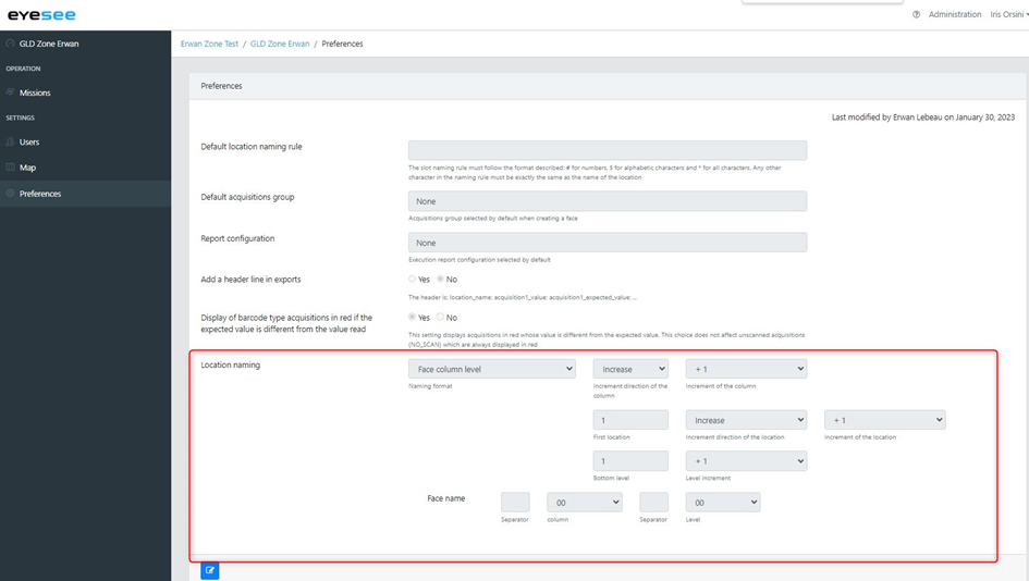
Thus, the fields will be automatically filled with these values when a new face is created.
2. Face creation with a CSV file
In this file, there are all the data about the face: name, physical dimensions, face addressing (=location codification).
A brief CSV file description:
- The first line is always ignored: it is the title of the expected parameters.
- A face begins with ###, then its name. a same file can describe several faces. In this case, a new line beginning by ### must be added.
- Next the face name, input the aisle width, and then all the default values that will be applied. The dimensions are in centimetres.
- Then, there are all the locations of each column, level by level (by descending order)
- Each column level is separated by a line including #LISSE
- A column change is indicated by a line with #ECHELLE
- For all these elements : upright (échelle in French), beam (lisse in French), and location, it is possible to replace a default value with one/more new values.
- The default location type is Normal (3 location types described next)
- For the constraints (required elements, minimum or maximum size, etc), it is easier to manage than in EYESEE Cloud, by changing the face
- In a face, a column needs to be exactly the same size (to the centimetre). If not, the import of the file will end up with a clear error report.
The locations
- NORMAL: the drone flies in front of the location and takes one or several acquisitions (according to the configuration)
- UNUSED: the drone flies / can fly in front of the location but does not take any acquisitions
- FORBIDDEN: the drone is not allowed to fly in front of the location, it is forbidden (ex: a forklift crossing point, a girder, a firebreak, etc)
Steps:
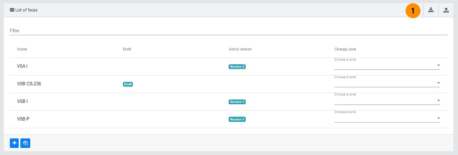
1. At the right of faces list, click on the icon « Import map »
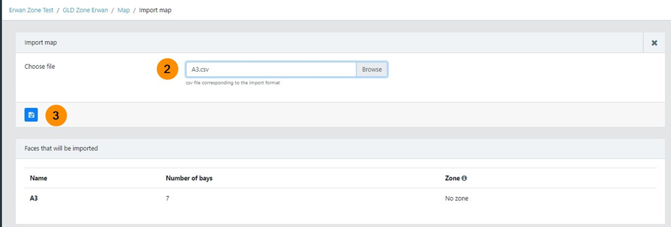
2. Choose the file.
3. Save.
The face is now created as a draft. By clicking on it, you can access the face information
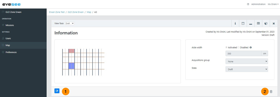
1. By clicking on the modification icon, the next parameters can be changed:
- Face general information: activated or disabled aisle width and its value, acquisitions group, state
- Linked with the face structure: bays, levels, slots, locations and flight constraints
Do not modify the uprights width to avoid a flight shift of the drone.
For the highest levels, it is recommended to enter a value 30cm smaller than the actual height to avoid unnecessary drone movements (for example to save battery or to avoid obstacle detection).
Ex: The highest level height is 190cm, so its entered value has to be 160cm.
You can modify a face only when no mission is attached to it.
2. Delete a face: click on the delete icon.
A face can be deleted only if there is no mission attached to it. If not, the mission needs to be removed first, and then the face.
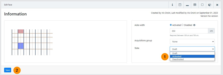
1. Once the verification and modifications are finished, you can change the face state and activate it. There are 3 different states:
- Draft (after a creation)
- Activated
- Deactivated
2. Save. Now, you can create a flight mission on this face.